Chevy express diagram vacuum van line 2009 need gm master technician tech S10 2000 injection emission intake Air flow express chevy 2500 chevrolet heating vacuum thru vents fan switch hoses works
Chevy Express Van Vacuum Hose Diagram - Q&A for G20, 5.7 & 6.2 Diesel
Chevy express hvac troubleshooting: q&a on vacuum diagrams, blend door Vacuum diagram hose chevy van 1986 chevrolet g10 line 1987 gmc under body Vacuum hvac auto repair
Auto hvac vacuum repair
Chevy express van parts diagrams: q&a for ac, blower motor replacementChevy express van rear 2009 diagrams add parts any would list Chevy express ac blows defroster2007 chevy express 2500 4.3 ac.
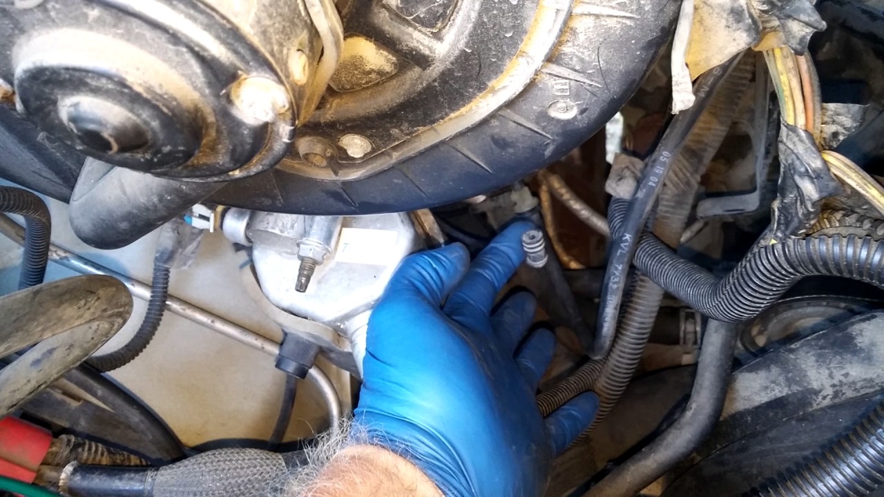
2000 chevy s10 secondary air injection system diagramChevy express van vacuum hose diagram Chevy express fix ac that blows out the defrosterVacuum diagram chevy g20 1990 van hose ac gm air control heater chevrolet tbi hvac tank vent core pump complete.

1986 chevy g10 van vacuum hose diagram
Chevy express van vacuum hose diagram .
.


Chevy Express Van Parts Diagrams: Q&A for AC, Blower Motor Replacement
Chevy Express fix AC that blows out the defroster - YouTube

Chevy Express Van Vacuum Hose Diagram - Q&A for G20, 5.7 & 6.2 Diesel

Auto HVAC Vacuum Repair - YouTube

Chevy Express HVAC Troubleshooting: Q&A on Vacuum Diagrams, Blend Door

Chevy Express Van Vacuum Hose Diagram | JustAnswer

2000 chevy s10 secondary air injection system diagram